How to Master B787 Engine – Power Plant – ATA 70
General
Boeing 787 Power Plant System is Powered By Two Rolls Royce Trent 1000D with Thrust rating of 70,200 Lb.
Consists of a Three Stage Rotor System N1, N2 And N3
Three Stages
| N1 | A Fan And A low-Pressure Turbine Section On A common Shaft |
| N2 (Connected to the gear box) | An Intermediate-Pressure Section And An Intermediate Turbine Section On A Common Shaft |
| N3 | A High-Pressure section And A High-Pressure Turbine Section On A Common Shaft. |
Fuel System

Fuel is supplied by fuel pumps from the fuel tanks, The Spar Fuel Valve and the engine Fuel Valve allow fuel flow to the engines.
| Spar Fuel Valve | Located In The Main Fuel Tank. |
| First Stage Fuel Pump | Adds Additional Fuel Pressure And Is Located In The Fuel Tank |
| Fuel/ Oil Heat Exchanger | Fuel Pre-Heating |
| Low Pressure Fuel Filter | Where Contaminants are Removed |
| Second Stage Fuel Pump | Dramatically Increases Fuel Pressure |
| Fuel Metering Unit FMU, Controlled by the EEC | Adjusts Fuel Flow to Meet Thrust Requirements |
| High pressure Fuel Filter | A Second Stage Filtering Before Fuel Enters the Engine |
| Engine fuel valve, Controlled by the EEC | Fuel flow is Measured After Passing Through the Engine Valve. |
Engine Oil System
The Oil System Provides Pressurized Oil to Lubricate And Cool The Engine Main Bearings, Gears, and Accessory Drives. It Also Provides Automatic Fuel Heating for Fuel System Icing Protection. Oil Pressure And Temp Are Measured By Dual TX’s.
| Engine Oil Pump Driven By The N2 Rotor Through The Accessory Gearbox | Pressurizes The Engine Oil (Engine Oil Pressure Is Measured Prior To Entering The Engine) |
| Oil Filter | Cleans Up The Oil |
| Fuel/Oil Heat Exchanger | Primary Heat Exchanger for Cooling the Oil And Heating The Fuel |
| Air/Oil Heat Exchanger | Provides Cooling When Fuel Flow Is Low OR There is High Fuel Temp |
| Main Bearings | Lubrication Processes |
| Gearbox | Lubrication Processes |
| Accessory Drives | Lubrication Processes |
| Scavenge Pump | Returns Oil To The Tank (Oil Temp Is Measured After Leaving The Engine) |
Ignition System
- Two Ignitors in Each Engine Controlled by the EECs, Only One Ignitor Is Used For Ground Engine Start’s And Two Ignitors For In-Flight Starts.
- DC power is the Normal Source for the Ignitors, And the Standby Power is The Backup Power.

Engine Thrust Reverser
- Hydraulically Actuated And Only Available On The Ground. The EEC Inhibits Reverse Deployment in the Air.
- Reverse Thrust Is Provided By A Cascading Vane System, It Provides A Reversal Of Only The Fan Airflow.
- On the Ground, It Allows Reverse Isolation Valve Actuation, Reverse Deployment, And Controls Thrust Limits.
- Reverse Thrust Levers Can Only be Raised when in Idle Position, And Only to An Intermediate Interlock Position. When in Interlock Position, Autothrottle will Disengage, Speed Brakes will Deploy, and the Reverser Becomes Activate.

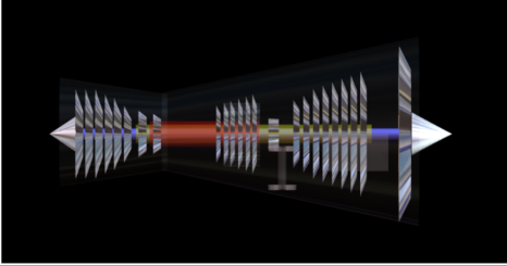
Cascading Vane System Shown With The Left Arrow & Blocker Doors With The Right Arrow

Reversers deployed
Note: The Thrust Levers Cannot be Moved FWD Until the Thrust Reverse Levers Are Fully Down.
- EICAS ENG REV LIMITED L or R Indicates a System Fault and is Displayed on the Ground if Reverser can Not Deploy or Reverse Thrust is Limited to Idle.
- EICAS ENG REV AIR/GND, Displayed with a Failure Of the Air-Ground Logic, that Prevents Reverse Deployment in Flight and An EICAS ENG REV COMMANDED (L or R), Displayed if the Thrust Lever is Not in the Down Position During Flight
| Thrust Reverse In Transit | Displays in AMBER |
| Thrust Reverse Fully Deployed | Displays in Green |
| Thrust Reverse stowed | REV Display is blank |
- Thrust Levers Are Positioned Either by the Autothrottle or Manually by the Pilot.
- Thrust Reverse is Manually Positioned by the Pilot.
Primary and Secondary Engine Indications
Primary Engine Indication

Secondary Engine Indication

- TPR, N1 and EGT are the Primary Engine Indications.
- The digital readouts display numerical values and dial/moving pointers indicate relative values.
- EGT: the EGT indication has a Max Continuous limit represented in the amber band. If the EGT reaches the Max Continuous limit, the digital indication, box pointer and dial all changes to the amber color. EGT indications are inhibited from color change in these cases:
- Takeoff or Go-Around For 5 minutes.
- Single Engine Operation For 10 minutes.

- The EGT Max Takeoff Limit is displayed by the Red Line. The Digital Indication, Box, Pointer, and Dial, will change to red.
- If N1, N2, N3, or EGT red line is exceeded, the Digital Read Out Remains red. When limits go back to normal range only the box will remain.
- Red can be cancelled and recalled by the CANC/RCL switch.
Secondary Automatic Engine Indication
Secondary Automatic Engine Indication are displayed, (when not selected for display)
- When The FUEL CONTROL Switch Is Moved To CUTOFF During Flight OR
- An Engine Fire Switch Is Pulled During Flight OR
- A Secondary Engine Parameter Is Exceeded OR
- Engine N2 Is Below Idle In-Flight OR
- A Start Selector Is In Start Position OR
- The fuel flow ENG L/R advisory is displayed.
- Note: The Secondary Engine Indication Can Not Be Cleared Until the Condition Is No Longer Present.
AutoStart
- The Engines Can Only Start Using the Auto Start System. Engine Rotation Is Provided By The Start Motor Function Of The Two Electrically Powered Starter/Generators. The Starter Motors Mechanically Drive The N2 Via The Accessory Gearbox.
- Simultaneous Engine Start is Preferred and Can Only be Established if Both APU Generators are Operative. If Both Engines are Commanded to Start with Inadequate Power Configuration, the Second Command is Ignored.
- Normal Engine Starts are Accomplished by the APU. If the APU is INOP, Start May be Accomplished by Using the FWD External Power. However, Connecting All Three External Powers FWD and AFT, Provides the Optimum Start Performance. (To get the Benefit of the AFT External Power Source, the Right Engine Must Start First).
If Both Starters Fail During the Start Process An Advisory Message ENG STARTERS (L or R) is Displayed on EICAS and the Electrical Synoptic Shows STARTERS in Amber Across Both Starters
| AutoStart Attempts To Correct On Ground (Only Two Engine Start Attempts) | AutoStart Is Aborted On Ground |
| – Hot Start – Loss of One Starter – Hung Start – Exceeded Starter Duty Cycle – No EGT -Compressor Stall | – No N1 rotation – Loss of both Starters |
Note: If AutoStart Is Unable To Correct The Start OR The AutoStart Is Aborted On The Ground, The EEC
- Shuts Off Fuel And Motors The Engine In Case Of An AutoStart Attempt But Does Not Motor the Engine if AutoStart Is Aborted.
- De-Energizes The Starters And Returns The START Switch To NORM
- Displays The EICAS Message ENG AUTOSTART (L or R)
In-flight Starts
For In-Flight Starts, It Will Continuously Try To Start The Engine Until The FUEL CONTROL Switch Is Placed In CUTOFF. In The Event Of High EGT, No Light Off, OR Hung Start, the EEC Will Discontinue The Start Momentarily To Take Corrective Action But Does Not Aboard The Start.
- An Auto Re-light System Is Provided For Flameout And Sub-Idle Stall Recovery. The System Is Energized Any Time On the Ground OR In-Flight When The Fuel Control Switch Is On RUN And The Engine Is At OR Below Idle Power.
- If An Engine Flameout Is Detected, The EEC Energizes Both Igniters To Recover The Engine
| Fuel Control Switches | Engine Control Panel |
| RUN – Opens The Spar Fuel Valve. – Arms The Engine Fuel Valve And Selected Igniters. Valve opening And Ignition Is By The EEC’s. CUTOFF – Closes The Engine Fuel Valve – Removes Ignitor Power – Unlocks The Engine Fire Switch Easy Said, The Fuel Control Switches, Control Ignition And Fuel | START – Commands The Fuel Spar Valve To Open And The Starter Motors To Energize. – Releases To NORM At Completion Of Start NORM – The Starter Motor is De-Energized |
Fuel Control Switches
| – Normal Position is IN and is Mechanically locked. – Unlocks Automatically for a Fire Warning OR when the FUEL CONTROL Switch is in CUTOFF. – Pull Out Position: Arms Both Fire Extinguishers. Closes the Spar Fuel Valves. Closes the Engine Anti-Ice Valves. Both Generators Off. Shuts off HYD Fluid to the Associated Engine Driven Pump and Depressurizes it. Removes Power to the Thrust Reverser. |
Electronic Engine Mode EEC
EEC Modes

-In The NORM Position, Sets Engine Thrust By Using The TPR (Turbofan Pressure Ratio) As the Controlling Parameter Based On Thrust Lever Position. (Either Automatically OR Manually By The Flight Crew).
-Maximum TPR Represents The Maximum Rated Thrust Available From The Engines.
-If The Required Signals Are Not Available To Operate In Normal Mode, The EEC Automatically Switches To Alternate Mode Using The N1 RPM As The Controlling Parameter. The Alternate Mode Provides Soft OR Hard Levels of Control. Soft And Hard Levels Are Determined By Whether The EEC Is Automatically Switched OR Manually Switched.
- In Both Modes The TPR And N1 Are Calculated By The FMC.
- The Autothrottle Remain Engaged Whenever The EEC Automatically Switches To Soft Alternate Mode And The N1 Indications Do Not Change. They Will Still Indicate Actual And N1 Red line.
- When Manually Switched To Hard Alternate Mode, The N1 Display Changes To Include The Commanded, Reference/Target, And Maximum N1 Indications.
- Automatic OR Manual Selection To The Alternate Mode Is Indicated By The EICAS Advisory Message ENG EEC MODE (L OR R) And will Illuminate On the Associated EEC Switch. Selecting The Alternate Mode On Both Engines Eliminates Thrust Lever Stagger At Equal Thrust Settings, OR Asymmetric Thrust When The Thrust Levers Are Operated Together.
- In Alternate Mode Thrust Protections Are Lost, As A Result Overboost Can Occur At Full Forward Thrust Lever Position. If Thrust Lever Position Commands An N1 Greater Than The Maximum Rated Thrust (Maximum N1) an EICAS message ENG LIMIT PROT (L OR R) is Displayed.
Note: In Alternate Hard Mode The NNC Procedure Calls For Autothrottle Disconnect And To Retard The Thrust Levers To Mid Position, To Prevent Exceeding The Thrust Limits. The Autothrottle May Be Reconnected After ALTN Is Selected.

EEC Computers
During Engine Start, The ECC Is Powered By The Aircraft Electrical Power. After Achieving Sufficient N2 Rotation, The EEC Is Powered By Its Associated PMA, (Permanent Magnet Alternator)
- Continuously Computes The MAX TPR.
- Monitors The Thrust Lever Position For Automatic Engine Control And Limit Protection
- Provides Protection Against Flameout During Periods Of Excessive Rain OR Hail Ingestion.
- Provides Overspeed Protection For The N1 And N2 Shafts. The N3, Is Indirectly Protected By The N1 And N2 Protection. The EEC Monitors The N1, N2, And N3 Rotor Speed And Can Command Reduced Fuel Flow If Any Of The Rotors Approach The Redline Limit. An EICAS Advisory Message, ENG RPM LIMITED is Displayed When Overspeed Protection Is Provided. If The Redline Limit Is Exceeded, The EICAS Caution Message ENG LIMIT EXCEED (L or R) Is Displayed. In Case If The RPM Limiting Fails and The Overspeed Condition Persists, The EEC Shuts Down The Engine.
- The Engines Are Equipped With A Secondary Air System Cooling & Sealing Airflow (SAS), A Valve That Regulates Intermediate Pressure (Stage- 8) And High Pressure (Stage-3) Bleed Air To Provide The Necessary Airflow To The Engines And Is Monitored And Controlled By The EEC’s.
Failure Of The SAS
| Valve In The Closed Position | Could Result in Ingestion of Turbine Gasses into the SAS, to Prevent this the EEC Increases Idle Power to Provide Enough Pressure to Prevent Gas Ingestion.On the ground and Below 80 knots an Advisory Message ENG CONTROL (L or R) Displays |
| Valve In The Open Position | Could Result In A Rapid Rise Of Temp, Resulting in Overheating of the Engine Bearings.An EICAS Warning ENG THRUST HIGH (L or R) OR a Warning ENG SEC AIR VLV (L or R)If the EEC Determines a Failed SAS Valve is Working Normally, it Removes All Protections and Full Thrust Becomes Available |
- Thrust Control Malfunction Feature Provides Protection Against Idle Thrust Asymmetry on the Ground, it will Shut Down the Engine if it’s Above Idle Speed and Not Decelerating Normally. An EICAS Caution message ENG FAIL (L or R) is Displayed
- TAP is your V2 Protection. When One Engine Fails, the TAP Reduces Thrust on the Operating Engine to Make Sure You Have Enough Rudder for Directional control.
Thrust Asymmetry Protection (TAP) is an Automatic function to Protect Against Excessive Asymmetric Thrust During Take-Off or Go-Around by Limiting Thrust on the Higher Thrust Engine. TAP Function is Only Available When Flight Controls are in Normal mode. (The EEC May be in Normal or Alternate Mode)
| During Takeoff | Reduces Thrust if Speed Decreases Below V2 Increases thrust when speed is above V2 |
| During Go-around | Reduces Thrust if Speed Decreases below Vref Increases Thrust when Speed is Above Vref |
Note: If TAP is INOP, EICAS Advisory Message THRUST ASYM PROT
Note: Don’t Confuse and Mix up Between Asymmetry Compensation And TAP (Thrust Asymmetry Protection)
- Asymmetry Compensation is a Feature of Flight Controls, When Ever A Yaw OR Roll Asymmetry Condition Exists (Engine Failure As An Example But Not Only) The System Automatically Counters It With Rudder Application.
- TAP’s Is Your V2 protection As Described Above.
- TAMS (Thrust Asymmetry Minimum Speed), and Its the Red Fence Shown at the Bottom of the Speed Tape, it gives you Extra Awareness of where the Minimum Control Speed is During an Engine Failure and is Always 10 Knots Above the Minimum Control Speed. If your Speed Drops Below this Red Fence, the AIRSPEED -AIRSPEED Aural Warning Sounds.
EEC IDLE MODES
Note: The EEC Selects Idle Modes Automatically
| Minimum Idle | For all Ground Operations and Most Phases of the Normal Flight. |
| Approach Idle Its Function Is To Decrease Acceleration Time for Go-Around Till Touch Down. | During Approach and Flaps are 25 OR the landing Gear is Selected DOWN. Thrust Idle is maintained 5 seconds after touchdown or when thrust revers is deployed |
| Icing Idle | Is Selected when Anti-Ice Selected ON |
| Ice Crystal Idle | When OAT is Between ISA and ISA+29, and the Altitude is Between 35,000 to 5000 feet |
Engine vibration
Airborne Monitoring and Engine Failure Alerting System
- The Airborne Vibration And Monitoring System Tracks Engine Vibration Levels (Rotor Imbalance), Which Is Displayed On The Secondary Engine Display, Including the Source. i.e., N1, N2 or N3. If The System Is Unable To Detect The Source Of Vibration A Broadband Is Displayed (BB), Which Is The Average Vibration Detected.
- When A Vibration Value Of 4 Units Is Reached The Secondary Engine, Parameters Are Automatically Displayed with A Reversed Readout (Black Numbers on a white Background).
- High N1 Vibration Is Normally Accompanied by Tactical Vibration, And OR Anomalies In Engine Parameters Usually During Thrust Adjustments.
- High N2 And N3 Vibrations, May Not be Felt By Anomalies In Engine Parameters Usually During Thrust Adjustments.
Engine Failure Alert System
| During takeoff (When the engine is producing less than the commanded thrust from 65 knots to slightly below V1) | Time Critical Warning -A siren followed by voice annunciation ENGINE FAIL -Illumination of the red MASRER WARNING lights -PFD and HUD warning message ENG FAIL |
| All other phases of flight | Caution Alert -A caution beeper with the illumination of the MASTER CAUTION lights -An EICAS message ENG FAIL (L or R), displayed when the engine decelerates below idle speed. or ENG THRUST (L or R) displayed when the engine is not producing the commanded thrust or airspeed is V1 – 5 knots or higher. |