How to master B787 Electrical System
It is a highly refined and automated aircraft, with automatic system configuration and load balancing. All systems of the aircraft are electrically powered; the only system pneumatically powered is the engine anti-ice.

Most of the electrical system components use the traditional 115 Vac or the 28 Vac power; however, some limited components require 235 Vac.
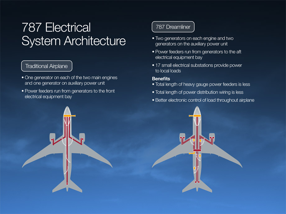
The fwd E/E bay is the main location for the 115 & 28 Vac’s, and the aft E/E bay is the main location for the 235 Vac’s, Conversion from one type of power to another is handled automatically. (E/E stands for Electrical and Electronic)
Ground operation
On the ground, the aircraft is powered by 115 Vac external power; fwd external power is normally used.
If the APU is not available, Aft external power may be used to reduce electrical load shedding. (Engine start with external power is accomplished by the use of the supplementary procedures)
A significant reconfiguration and load shedding are to be expected during external engine start, such as the first officer EFB, right CCR, MCP, and numerous cabin equipment
Main System
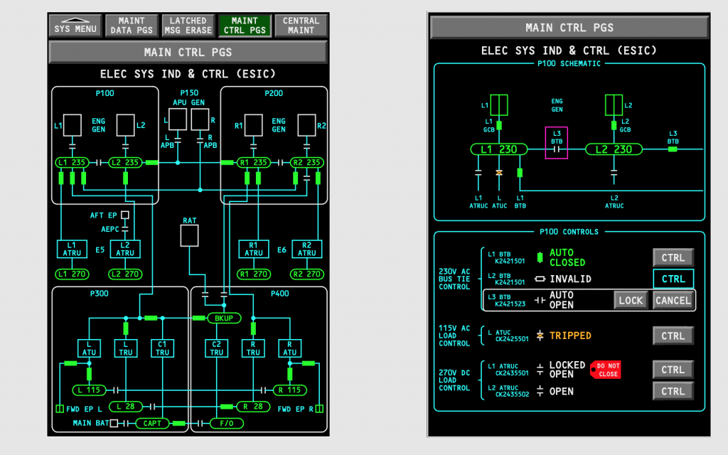
The system consists of four main 235 Vac buses (L1-L2-R1-R2).

General notes
- Note: The 235 Vac power is used to operate high load electrical components such as Hydraulic pumps, Engine starts, and the Nitrogen Generation System.
- Note: The 115 Vac & 28 Vac buses power some primary loads directly, approximately 25 AC loads & 200 DC loads.
- The electrical system uses two types of distribution methods: Primary & Secondary, primary power is used for high loads directly from the main buses AFT & FWD E/E bays.
- The main wheel brakes are electrically powered. Powered by 4 supply units and regulates power to the brakes. Each unit has two separate 28 Vac inputs, one extracted from the primary power source, and a secondary back power system from the main 28 Vac battery.

Load Shedding
- The aircraft is equipped with load inhibits and load shedding features.
| Load Inhibit | Inhibits certain loads that are not required for that operational phase, or if another system needs the power. |
| Load Shedding | Shedding in a priority order, to shed loads as necessary to maintain the capacity of available power sources to operate higher priority items. Example, Is the shut down of the CAC’s during ground engine start. |
Engine generators notes
Two Starter/Generators 235 Vac (L1-L2-R1-R2)
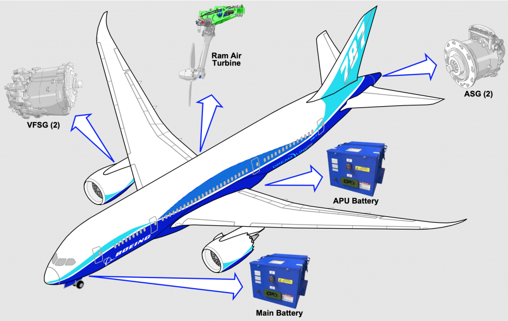
- Each engine, two starter/Generators are directly connected to the Engine gear box, producing variable frequency power proportional to the Engine rotor speed.
- Both engine starters are used for engine start, but nevertheless the engine may be started with only one generator. The start will be slower than the normal start.
- Power for engine start may be provided by the APU, opposite engine generators or external power.
- Both generators on each side will provide a variable frequency of 235 Vac to the AFT E/E bay, were power is distributed. Four main buses (L1-L2-R1-R2) each powered by its respective generator line. Automatic protection ensures that only one source is applied to the main bus at a time.
- Each generator has a drive disconnect mechanism that allows the generator to be mechanically disconnected from the engine. Depending on the fault condition, can be disconnected manually or automatically. (DRIVE DISC), once disconnected cannot be reconnected.
APU generators notes
Two Starter/Generators 235 Vac (L-R)
- The two generators are directly connected to the APU gearbox, producing variable frequency power proportional to the APU speed.
- Only one starter is used for APU start.
- APU battery, external power or engine generators may start the APU, indication to start the APU on battery only is both CDU’s available.
- The APU start is fully automatic and sequenced as follows
- A DC powered fuel pump in the L, main tank comes ON
- The APU inlet door opens
- Starter activation and Ignition
Note: If APU started on battery power, the Right starter is always used.
- In case of the loss of three generators or more, the APU will start automatically regardless of APU selector position.

Large Motor Power System
Provides power to the Large Motor Power System
- The electrical system uses two types of distribution methods: Primary & Secondary, primary power is used for high loads directly from the main Buses AFT & FWD E/E bays.
- Automatic protection ensures that only one source is applied to the main bus at a time, the system automatically determines the power source priorities for the current condition for best efficiency.
PECS
PECS (Power Electronics cooling system): Dissipates or in other words clears the heat by cooling the systems, from these high voltage motor controllers.
RPDU
RPDU (Remote Power Distribution Unit): Is used for lower amps loads through a decentralized network, of 17 Remote Power Distribution Units.
Batteries
Two 28 Vac batteries, the Main battery is in the FWD E/E bay and the APU battery is located in the AFT E/E bay.
NOTE:
Once the battery is selected ON, the ON- Ground Battery Only Mode is energized, it takes the LEFT CCR between 2 and 3 minutes to boot up. And becomes online when the captains inboard and lower display are available.
- The main battery is used as a backup 28 Vac power for the brakes.
- The main battery provides standby power for RAT deployment.
- Main battery indications
- Low voltage, will show an advisory message (MAIN BATTERY LOW) on EICAS
- AMPS (white value), shows rate of charge or discharge
- CHG (white), shows battery charging
- DISCH (white), shows battery discharging, and indicated by an EICAS message (MAIN BATTERY DISCH)

RAT (Ram Air Turbine)
Deploys Automatically or Manually and can provide standby electricity for an unlimited time with no altitude or airspeed restrictions, it also generates hydraulic pressure.
Automatic deployment of the RAT
- Both engines failed
- All three hydraulic system pressure are low
- Complete electrical loss of the Captain’s and First officer’s flight instruments.
- Loss of all four electrical motor pumps (EMPs), including faults in the flight control system during approach.
- Loss of all four EMPs, with an engine failure during take-off or landing.

28 Vac Permanent Magnet Generators
(L1-L2-R2) generators are the primary source of power to the flight controls, that ensures power independent from rest of the electrical system.
This independed power system ensures that regardless of the electrical system status, the flight control power remains available if one engine is still Rotating.
BPCU (Bus Power Control Unit)
It manages electrical dynamic loads (Load Management and protection)
It provides flight deck control and indications also, (transfers power functions).
Power Modes
The electronic controllers determine which group of loads are to be powered for any Mode.
Types of Modes
Towing power Mode
The Towing Panel allows for Battery testing, indicating current battery state verses time (HIGH-60/MEDIUM-30/LOW-15 min’s) before selecting the Power ON.
(Available is the Captains ACP & Flight interphone, Dome lights, Aisle stand flood lights, NAV lights and Brakes)
On Ground Battery only Mode
( Available is the Captain & First officers ACP, flight interphone, Captain inboard DU, lower DU, MCP, APU start, Wing fuelling panel, Left (VHF/TCP/DSP/MFK/CCD/CCR), FMC, AHRU L&R, Ground crew horn, Engine/APU fire detection, Miscellaneous lighting and Brakes).
Ground handling Mode
- Has priority over On-Ground Battery Only
This Mode is active with the first FWD external power being connected and NOT SELECTED ON. (No other power source).
(Available is the lower DU, left MFK & CCD, L&R CCR, APU start, Equipment cooling fans, Engine & APU fire detection, (Cargo lighting and loading lights, Service compartment lights and the Actuation & handling system), Wing fueling panel and Battery chargers, most of the items are service and cargo related, the battery switch ON is not required.
Ground service Mode
- Is active when switching the GROUND SERVICE to ON from the Master attendant switch panel, while in Ground handling Mode.
- In addition to all loads energized by the Ground handling Mode, two additional significant loads are energized.
- Cabin system (limited operation)
- Cabin lighting (limited operation)
External Power on Mode
One FWD External Power Connected & selected ON
Active is Flight deck equipment, controls and indications, cabin systems & lighting limited operation and the PECS single loop only.
Two FWD External Power Connected & selected ON
In addition to the above active systems is the NGS limited operation, HYD limited operation, IFE limited operation, cabin system and lighting basic operation and PECS both loops.
(Packs & Cargo heat are INOP with only FWD external power)
In-Air Rat only Mode (Standby Power)
Is active with the loss of all electrical power to the Captain’s & First officers flight instruments, in that case the RAT will energize the captains flight instruments with some essential equipment including flight controls, navigation and communications.
Energized equipment by the RAT are as follows.
Captains inboard & outboard DU’s, lower DU,MCP, PFC, ECL, FMC limited operation, Autopilot limited operation, Autoflight system, Captain’s & First officer’s ACP’s and the flight interphone, LEFT( VHF/TCP/DSP/MFK/CCD/CCR), LEFT & RIGHT (IRU/AHRU/INR), Centre pitot heat, Engine/APU fire detection and miscellaneous lighting.
INOP systems include TAT, Autothrottle, LNAV/VNAV, FMC predictions and thrust limits, TAP, Flaps & Slats, Stabilizer trim, Packs, HUD’s, HF, SATCOM, TCAS, GPWS, Transponder, WX radar, External lighting, Wipes, and Window heat.
In-Air battery Only Mode (Standby Power)
The IN-AIR battery Mode energizes the same equipment as the RAT Mode, with exception of the Centre Pitot heat.
Circuit Breakers
Two types of CB’S
| Electronic Circuit Breakers ECB’s | Provides indication and remote control, can be open or closed using CBIC. |
| Thermal Circuit Breakers TCB’s | Provides indication ONLY |
Reset of CB’s is Not recommended by Boeing, unless instructed by a NNC or maintenance During flight, decision should be based on EICAS Amber Alerts only, and not just status messages.

Conditional Situations
| One Engine running and the other engine shut down with the APU online. | The APU Generator powers the 235 Vac two main buses on the side of the none running engine, and the running engine powers both buses on its respective side. |
| During flight, One generator fails | The system will automatically reconfigure to maintain power to all Four 235 Vac main buses, with the remaining generators. |
| During flight, Two generators fail | The system will automatically reconfigure to supply power to the essential components but expect to see a list of LOAD SHED items. |
| In case of all generators fail and the APU is not available | The RAT will deploy automatically |
| Flight on battery Only | It would power the same components as the RAT, except for the centre pitot heat, and is time limited. |