How to master B787 Flight Management and Navigation System – ATA 34
- The FMS Consists Of A Series Of Automated Functions To Assist The Flight Crew During Operation. Precise Guidance Is Provided For Both Navigation And In-flight Performance. Highly Accurate Automatic Fuel Monitoring Is Also Provided.
- The FMS Uses Navigation And Performance Databases, As well As data Entered Directly By The Flight Crew OR Received Through Datalinks.
Company Datalink Communication Methods
Automatic
Data Is Uplinked And/or Downlinked Automatically Between The Airplane And Flight Operations
Manual
Data Is Manually Requested And Transmitted By The Flight Crew or Flight Operations
Types Of Communications
Types Of Communications
- The FMS Also Automatically Tunes And Identifies Navigation Radios, That Include (ILS/VOR Among Routes/Dep And Arrival Procedures).
- The FMC Is Certified For Area Navigation (RNAV) If The Aircraft Has GPS OR Navigation Radio Updating.
- The Control Display Unit (CDU) Is An Emulated Unit Used By The Flight Crew To Communicate With The FMC Through The Multifunction Keypad (MFK’s)
FMS Guidance
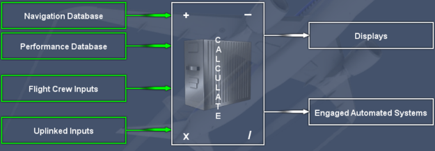
Navigational Guidance Displayed
On the ND Map, the PFD, And PFD Mini-Map.
Performance Guidance
- On the PFD as Pitch Commands and Speed Commands
- On the ND as Optimal flight Path Displays
- On the Engine Instruments As Thrust Settings-On the CDU As Recommended Speed, Altitude, And Step Climb.
Flight Management Computers
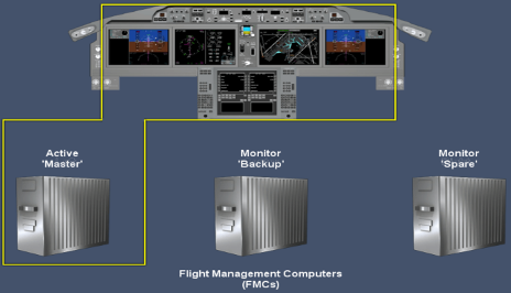
Three Independed FMC’s, (LEFT/Right/Centre), When The Airplane Is Powered Up One Of The FMC’s Is Selected To Accomplish All Of The Flight Management Tasks And Is Designated As The Master. The Other FMC’s Monitor. One Is Designated As Backup And The Other As Spare.
If a System Fault Occurs, the Backup becomes the Master, and the Spare becomes the Backup.
Introduction To The Navigation System
Primary Navigation
– Air Data Reference System (ADRS)
– Inertial Reference System (IRS)
– Global Positioning System (GPS)
Radio Navigation
– 2 Distance Measuring Equipment (DME)
– 2 Instrument Landing System (ILS)
– 2 Navaid Identifier Decoding
– 2 VHF Omnidirectional Range (VOR)
Flight Management
– Present Position Updating
– Polar Operations
Air Data Reference System
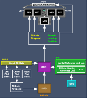
Sends Trusted Voted Air Data of (Altitude And Airspeed), The ADRS is completely Independent of the IRS.
They Receive Data From The Following Components
- 6 Air Data Modules
- 6 Static Ports
- 3 Pitot Probes
- 2 Angle Of Attack Sensors
- 1 Airframe Mounted (Total Air Temperature Probe)
- 1 (Total Air Temperature Probe) In Each Engine
If Airspeed Data To The PFDs Is Invalid, Backup Airspeed (AOA SPD) Is Automatically Provided By The IRS, And Backup Altitude Is Provided Automatically By The GPS. In The Event Both Of The Backup Systems fail The Integrated Standby System Is Used.
Inertial Reference System
| IRU’s Send The Following 6 Information’s | The Information Is Then Sent To 5 Different Units | The Information Is Then Sent To 5 Different Units |
|---|
| Altitude Heading Rate | Position Airspeed Attitude | Flight Deck Display Flight Controls Other Systems Flight Management System Engine Controls |
| AHRU’s Send The Following 3 Information’s | The Information Is Then Sent To 3 Different Units |
|---|---|
| Altitude Heading Rate | Flight Deck display Flight Controls Other Systems |
Inertial Reference System – Failures


GPS Will Provide The Necessary Information For The FMC Through The Integrated Navigation Radios (INR’s), Such As (Flight Planning, Navigation And Performance Information), (The CDU POS INIT Page Displays The SET HDG Prompt). However, Many Functions Will Be Lost
| Inoperative | AFDS Modes | Inoperative Navigation Functions | Inoperative PFD Functions |
|---|
| LNAV VNAV TO/GA LOC | G/S FPA TRK HOLD/SEL HDG HOLD/SEL (*) | FMC VNAV Pages FMC Performance Predictions ND Wind Direction And Speed (Wind Arrow) | PFD Heading (*) |
- (*) HDG HOLD/SEL & PFD Heading Will Function Normally When Heading Is Entered On The POS INIT Page.
- ND Map Display Following IRS Failure References TRK
- Autobrakes Become Inoperative
- The Use Of The Integrated Standby Flight Display (ISFD), Which Receives Its Data From The Centre Pitot/Static Modules.
- The ISFD Altitude, Attitude, And Airspeed Are Independent Of IRU And AHRU Value.
- The ISFD Altitude (ISFD ALT) And Airspeed (ISFD SPD) Are A Backup For The PFD’s In The Event That Both ADR’s And GPS/IRS Are Not Available.

- Power To The Left IRU And Left AHRU Is Controlled By The Left Switch On The Overhead Panel And Visa versa With The Right Side.
- When Switches Are Turned ON, The Units Enter The Align Mode With An EICAS Message In White (IRU ALIGN MODE L+R) With The Attitude Indication Removed From The PFD’s.
- When The Alignment Is Complete, The IRS Navigation Mode And the IRU ALIGN MODE L+R Is Removed.
- IRS On Battery Light Illuminates Only When IRS Are Aligned. If Electrical Power Is Lost After IRU Alignment Is Complete The Hot Battery Bus Continues To Supply Power To The IRS. On The Ground, A Horn Sounds In The Nose Wheel Well To Alert The Ground Crew That The IRS Are Depleting The Battery)
- If The Airplane Stops For An Extended Period The IRS Initiates An Automatic Realignment And Is Refined Until The Airplane Moves Again. (There Is No indication Of Automatic Realignment)
- In The Event Of Loss Of power During Flight The IRU Has The Ability To Realign In Flight, Provided The GPS Is Functioning. Once Restored Altitude Information Becomes Available Within Seconds And A Full Navigation Capability Is Restored Within 10 Minutes.
- Independent Left And Right GPS Receivers Supply Independent And Very Accurate Position Information To The IRS.

- The Alignment Time Is Displayed In The Upper Left Corner Of The ND And Normally Takes 7 To 10 Minutes At Mid Latitudes And May Take Up To 17 Minutes At High Latitudes. (The Airplane Should Not Be Moved During Alignment).
- All GPS Tunning Is Automatic.
- There Is NO Requirement To Enter The Airplane Position If The GPS Is Operating Normally, However If Dashes Are Replaced With Boxes The Present Position Must Be Replaced. Present –Position Updating Priority Is Based On The Availabilty Of Valid Data. If GPS Data Is Not Available OR Inhibited, The FMC Reverts To Radio-Inertial Data.
- If Both GPS And Navigation Radios Are invalid, the FMC Uses IRU’s Data. Updating Priority is Based On The Availability Of Valid Data As Follows, (GPS/IRU Inertial Data)– (GPS)– (Radio/IRU Inertial Data)–(Radio)– (IRU Inertial Data).
