Two AC Pumps In The Centre Tank (L &R) And Two AC Pumps In Each Main Tank (FWD and AFT).
If All Pumps Fail, Each Engine Can Suction Feed From Its Respective Fuel Main Tank, However Suction May Not Provide Adequate Fuel Flow At High Altitudes. (Suction Feed from The Centre Tank is Not Possible).
Although Any Fuel Pump Can Be Configured To Feed The APU, The Normal Automatic Supply To The APU On The Ground Is The Left AFT PumpRegardless Of The Pump Switch Position. If No AC Power Available To Start The APU (AC Fuel Pump), Fuel Pressure Is Automatically Supplied By A DC Fuel Pump Located In The Left Main Tank.
Centre Tank Pumps
Each Centre Tank Pump (L &R) Feed Their Respective Side, They Are Designated As Override/Jettison Pumps And Have A Higher-Pressure Output To Ensure Centre Fuel Being Used First.
In Non- Normal Conditions, One Centre Tank Pump Can Feed Both Sides By Opening The Crossfeed Valve, In This Situation The Override/Jettison Pump Will Feed Both Engines And Reduce The Chance Of An Imbalance.
Main Tank Pumps
With The Main Tank Pumps ON And The Centre Pumps OFF, The Scavenge System Automatically Transfers Any Remaining Centre Fuel To The Main Tanks. The Fuel Transfer Begins When Either Main Tank Quantity Is Less Than Approximately 16 Tons Depending On Fuel Density. (The Scavenge System Is Inhibited If Engines Are On Suction Feeding)
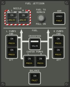
Overhead Panel
Allows Control Of The Fuel Pumps, The Cross-Feed Valve, And The Balance System. Just Above The Panel Is The Jettison Panel.
In Some Non-Normal Conditions, Electrical Power Is Insufficient To Operate All The Fuel Pumps And Will Automatically Determine The Best Pumps To Operate And Shed The Others. Indication Of The Affected Pumps Will Show On The Over-Head Panel And The Fuel Synoptic By A LOAD SHED Next To The Pump.
Fuel Balance System
Fuel Balance
The Fuel Balance System Can Transfer Fuel Between The Main Fuel Tanks In All Phases Of The Flight Including Ground With All Engines Shut Down And The APU Running.
Fuel Balance Is Inhibited In Case Of, (Refuelling OR Defueling (Fuel Control Panel In Use), The APU Is Off, Fuel Balance System Failed, Centre Tank Pumps ON, Both Engines Running On Ground, And In Flight With The Jettison System Active)
FUEL IMBALANCE
The FUEL IMBALANCE Message Appears And The EICAS Fuel Display Changes To The Expanded Display And A Solid AMBER Fuel Imbalance Pointer Displays For The Tank With The Lower Quantity.
By Switching The Fuel Imbalance ON, The Automatic System Transfers Fuel From One Tank To The Other. Fuel Is Transferred Through The Jettison/Defueling Valve Of The Tank With The Higher Quantity, To The Inboard Refuel Valve Of The Tank With A Lower Quantity. The Process Will Stop When The Difference Is Within 100 kgs.
Crossfeed Valve
It Is Manually Controlled By The Crossfeed Switch And Operates So That Fuel From One Fuel Manifold Be Delivered To The Opposite Engine. In Case Of A Disagreement Of the Switch With The Valve Position, The Amber VALVE Light Illuminates And An EICAS Message FUEL CROSSFEED Is Displayed.
When The Crossfeed Switch Is Turned ON And The Valve Opens, A Message FUEL CROSSFEED ON Is Displayed.
If The Fuel Is Going In The Wrong Direction The Imbalance Pointer Will FLASH IN AMBER
Fuel Jettison System
NOTE: The Main And Centre Tank Pumps Must Be ON To Jettison Fuel
Can Jettison Fuel From All Tanks When Selected By The Pilot. An Automatic Shutoff Will Maintain A Minimum Level Of Fuel In The Main Tanks. The Jettison Is Accomplished By Opening The Main Tank Defuel/Isolation Valves And Centre Tank Isolation Valves, To Move The Fuel To The Jettison/Refuel Manifold.
It Then Is Jettisoned Overboard Through Jettison Nozzle Valves Located Inboard Of Each Aileron. The nozzle Valves Cannot Open On The Ground.
The Fuel Jettison Panel Has An ARM Switch, A FUEL TO REMAIN Selector And Two Nozzle Selectors.
Arming The System Causes: – TO REMAIN to replace The FUEL TEMP – GROSS WT to replace The SAT TEMP
TO REMAIN Value Is Set At The Fuel Quantity For Maximum Landing Weight MLW.
The Fuel Synoptic Will Display TO REMAIN Value And The Remaining Time (JET TIME) To Arrive To The (TO REMAIN Value).
The Fuel TO REMAIN Selector Can Be Pulled And Rotated To Increase OR Decrease The Remaining Quantity, But Regardless Of The Selection At Least 3946 kgs Will Remain In Each Main Tank.
With The Fuel Jettison Switch Armed And One Jettison NOZZLE Switch Is ON, The Main And Centre Tank Valves Will Open.
Fuel Temp And Quantity
Are Displayed On EICAS And The Fuel Synoptic. If Fuel Temp Approaches Maximum OR Decreases To Freezing Temperature, The Fuel Figure Will Display In AMBER.
Nitrogen Generation System (NGS)
Provides Automatic Full Time Flammability Protection. It Generates Nitrogen Enriched Air Pumped Into The Fuel Tanks To Displace Fuel Vapor As Fuel Is Consumed. The Nitregen Enriched Air Minimizes Fuel Flammability.